Drone Log #2: Building and Validating an Autonomous Drone with Object Tracking
1. Project Overview
- The drone detects a target using an onboard camera and an AI object detection model.
- It estimates the target’s position relative to the drone.
- It calculates orbit kinematics and orbits the target.
- The final system was tested in both simulation and real flight.
- The project used a Jetson Orin Nano 8gb companion computer and a PX4 Pixhawk 6C flight controller.
2. Flight Test Run
Flight test: the drone detects the red ball and autonomously performs an orbit around it using onboard vision and control software.
3. Primary Objective
Develop a drone system capable of:
- Detecting a designated object.
- Continuously tracking its image position.
- Converting visual tracking data into flight commands.
- Approaching or orbiting the target at a controlled distance.
- Maintaining safe and predictable behavior when tracking is lost.
Success Criteria
Possible criteria to include:
- Stable object detection during flight.
- Acceptable inference latency.
- Smooth tracking commands.
- Successful orbit behavior in simulation.
- Successful orbit behavior during outdoor testing.
- Safe response to invalid, stale, or missing tracking data.
4. System Functions
- Capture camera frames at at least 30fps. 100% Uptime.
- Run an object detection model. 100% Uptime.
- Detect the intended target with a confidence of 80% or more.
- Ability to lock onto intended target and stay locked on 90% of the time or more during orbit pre-stage mission step.
- Calculate the target’s offset from the image center compared to object detection boundary box.
- Estimate the target’s relative position or distance.
- Generate drone movement commands.
- Ability to center the drone on the target.
- Transition into orbit behavior.
- Monitor system health and telemetry.
- Run drone commands such as: Stop, hold, land, or return safely when required.
5. Safety Requirements
- The drone shall not start autonomous movement without permission from the ground station.
- Autonomous movement shall require a healthy flight-controller connection.
- Tracking data older than the permitted timeout shall not be used.
- Loss of target shall cause the drone to hold rather than continue using stale commands.
- Low battery shall block or terminate the autonomous mission.
- Loss of GPS or invalid position data shall trigger a defined fallback.
- The operator will have the ability to cancel the mission at all times from the ground station or with an RC controller.
- Landing and return-to-launch behavior shall remain available independently of the vision system.
- Vision commands shall be bounded to prevent sudden or excessive movement.
- Simulation testing shall be completed before outdoor autonomous flight.
| Hazard | Detection Method | System Response |
|---|---|---|
| Target lost | Detection timeout | Hold position |
| Stale camera data | Timestamp validation | Reject command |
| Low battery | Telemetry threshold | Abort or land |
| GPS loss | Position-health monitoring | Hold or return |
| Excessive command | Command limits | Clamp or reject |
6. System Architecture
Camera Task
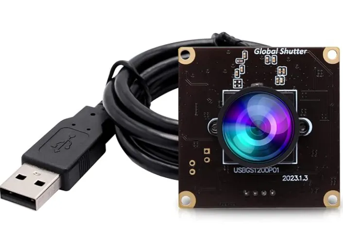
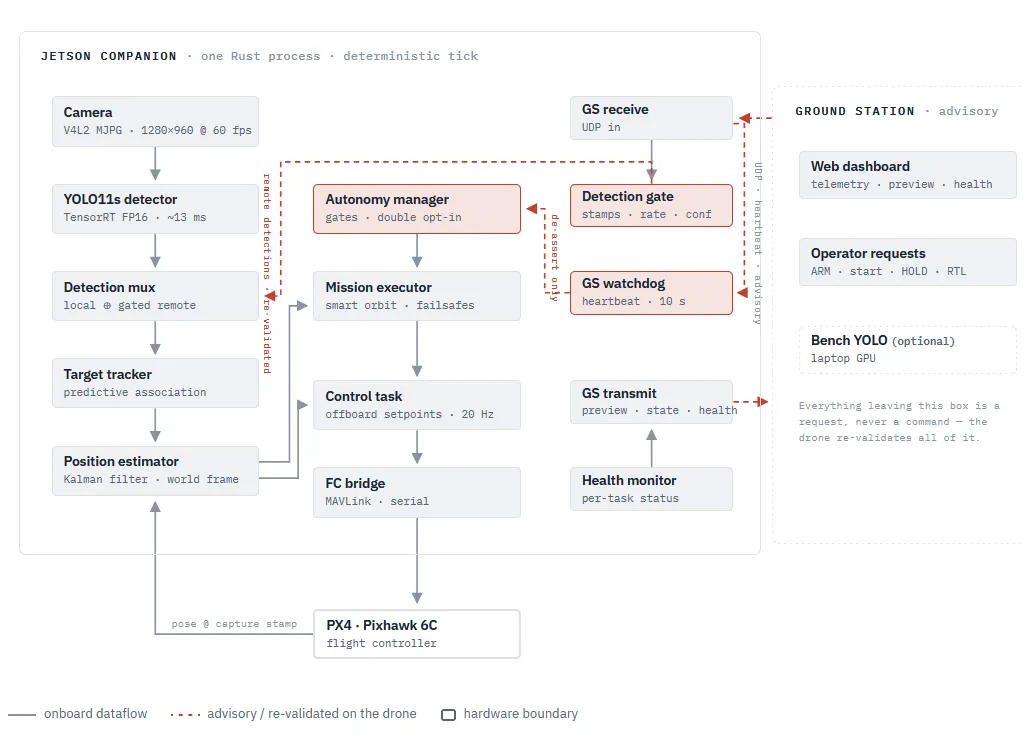
A capture thread drains the camera driver continuously (V4L2, MJPG, 1280×960 at 60 fps) while worker threads decode JPEG into a newest-frame-wins slot. The main loop blocks on decoded frames, which paces the whole graph to the camera. Every frame carries a capture timestamp from the driver clock.
AI Object Detection
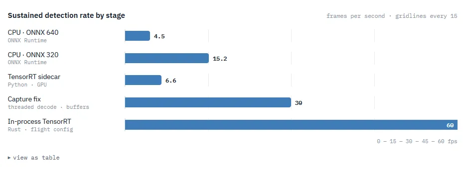
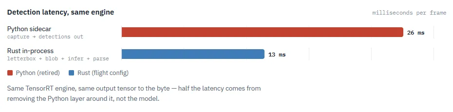
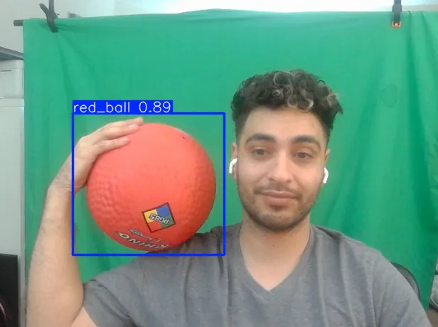
The YOLO11s TensorRT engine, run on a native-resolution crop predicted around where the target will be at this frame’s capture time (full frame when searching). Using Rust instead of Python allowed me to reduce the detection latency by half. It also enabled the Jetson to run the camera at 960p at 60FPS with a Detection latency of only 13ms!
Target Tracking
Associates each detection against a constant-velocity prediction of the target’s image position rather than its last seen position, with an acceptance gate that widens the longer the target has been missing and re-tightens on reacquire. Monocular range comes from the bounding-box size via a bench-calibrated constant.
Position Estimator
A Kalman filter in world coordinates. Each detection is projected using the drone’s attitude and position at the frame’s capture time. Pairing pixels with a 40 ms-stale pose was the single biggest source of wobble in early versions. The projection accounts for the 45°-down camera mount and a calibrated compass-bias correction.
Distance Estimator
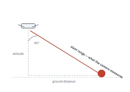
Range to the center of the ball comes from my camera and the size of the ball in the image. Measure the ball’s diameter in pixels, and use that to derive the distance using the formula shown below.
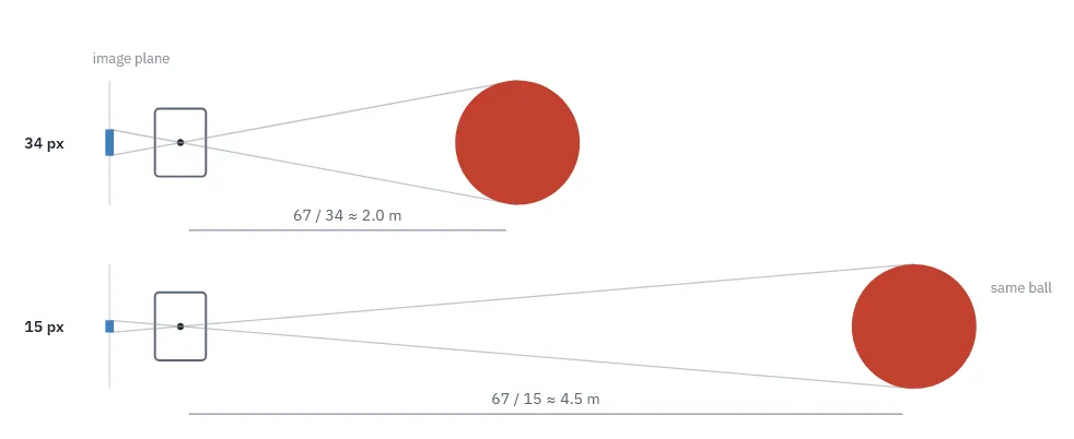
Calibration is easy:
Put the ball at tape-measured distances (2–6 m), read what the estimator reports, and fit k. The calibrated result on hardware: 2.81 m reported at 2.80 m true, σ = 1.4 cm.
Autonomy Manager and Mission Executor
Runs validated mission plans (takeoff → scan → track → approach → orbit → land) with an explicit safety gate on every transition. The orbit is “smart”: while tracking, the executor averages the estimator’s target positions, freezes the mean as the circle center, then flies the circle by geometry. A detection dropout mid-orbit cannot disturb the flight path.
Control Task
Turns tracking error and mission setpoints into PX4 offboard commands at 20 Hz, behind its own gates: battery floor, command-staleness timeout, yaw-rate clamp, and offboard/arming preconditions.
Safety Supervision
Checks telemetry health, detection freshness, battery state, connection state, and command limits.
7. Simulation
Simulation lets us test out my code and logic before we ever launch the drone. I used the Gazebo sim that has presets for my drone: the Holybro x500 frame. Once the Gazebo sim is set up, we can use a virtual camera inside the sim and stream the images out. These images feed our AI detection model.
Validated:
- Stable object detection during flight.
- Smooth tracking commands.
- Successful orbit behavior during missions.
- Safe response to invalid, stale, or missing tracking data.
| Area | Gazebo Simulation | Outdoor Test |
|---|---|---|
| Target detection | Simulated environment with AI detection model | Real camera with AI detection model |
| Flight disturbances | Idealized environment | Windy environment and potential GPS disconnects |
| Orbit geometry | Easy to observe | Verified through recorded flight |
| Timing | Repeatable | Subject to compute and communication latency |
| Safety | Validate Safety Requirements and Fail safes | Required strict operational controls |
| Main purpose | Validate logic | Validate the complete physical system |
8. Jetson Vision-Pipeline Specs
| Measurement | Result |
|---|---|
| Camera resolution | 960p |
| Camera frame rate | 60 FPS |
| Inference latency | ~13 ms |
| Target | Red ball |
| Typical confidence | ~80%+ |
| Compute platform | Jetson Orin Nano |
9. Real-World Results
10. Future Work
- Collect a custom image dataset using the actual camera and target.
- Improve detection confidence under varied lighting.
- Quantitatively measure orbit-radius error.
- Measure target-loss frequency.
- Add position-accuracy logging.
- Improve recovery after temporary target loss.
- Test multiple target distances.
- Add obstacle detection and avoidance using LiDAR.
- Expand from a red-ball tracker to more ambitious targets.