Autonomous Drone: Object Tracking using ROS2, YOLO Detection, PX4, a Raspberry Pi 4, and the Pixhawk 6C.
Code on GitHub
In this project, I developed an autonomous target-tracking system for a drone using a custom-trained YOLOv8n object detection model and the Robot Operating System 2 (ROS2). The goal was to have a drone autonomously track and visually lock onto a target (a red ball) by adjusting its heading (yaw) based on real-time camera feed data. To safely develop, test, and tune the control loops without risking hardware crashes, I used PX4’s Software-in-the-Loop (SITL) simulation environment. This allowed me to pipe live ROS control code directly into a simulated drone via MAVLink, mirroring exactly how the code would execute on physical hardware.
Code Highlights:
- Testing the USB camera with OpenCV
- Testing YOLOv8n on camera frames before ROS integration
- Training a custom red-ball YOLOv8n model from a Roboflow dataset
- Publishing camera frames into ROS 2
- Running YOLO inference inside a ROS 2 node
- Converting bounding boxes into normalized tracking error
- Turning image error into yaw commands
- Sending safe PX4 Offboard setpoints through MAVSDK
- Using MAVLink / MavlinkDirect for lower-level commands like orbit
GITHUB: https://github.com/danielengineer92/dronetrack_pi_ros
The Hardware Setup
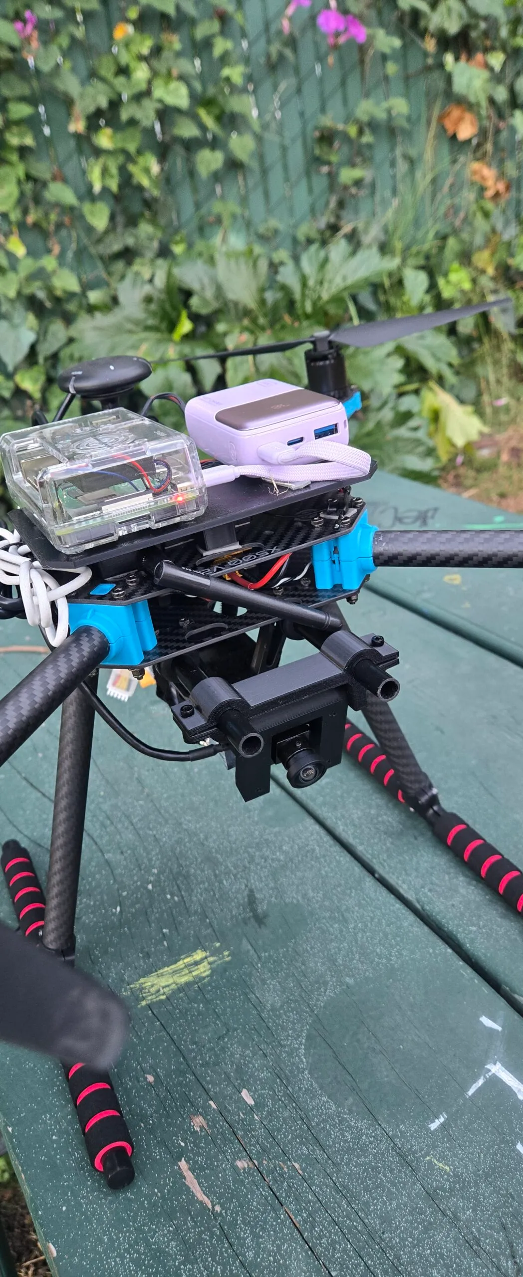
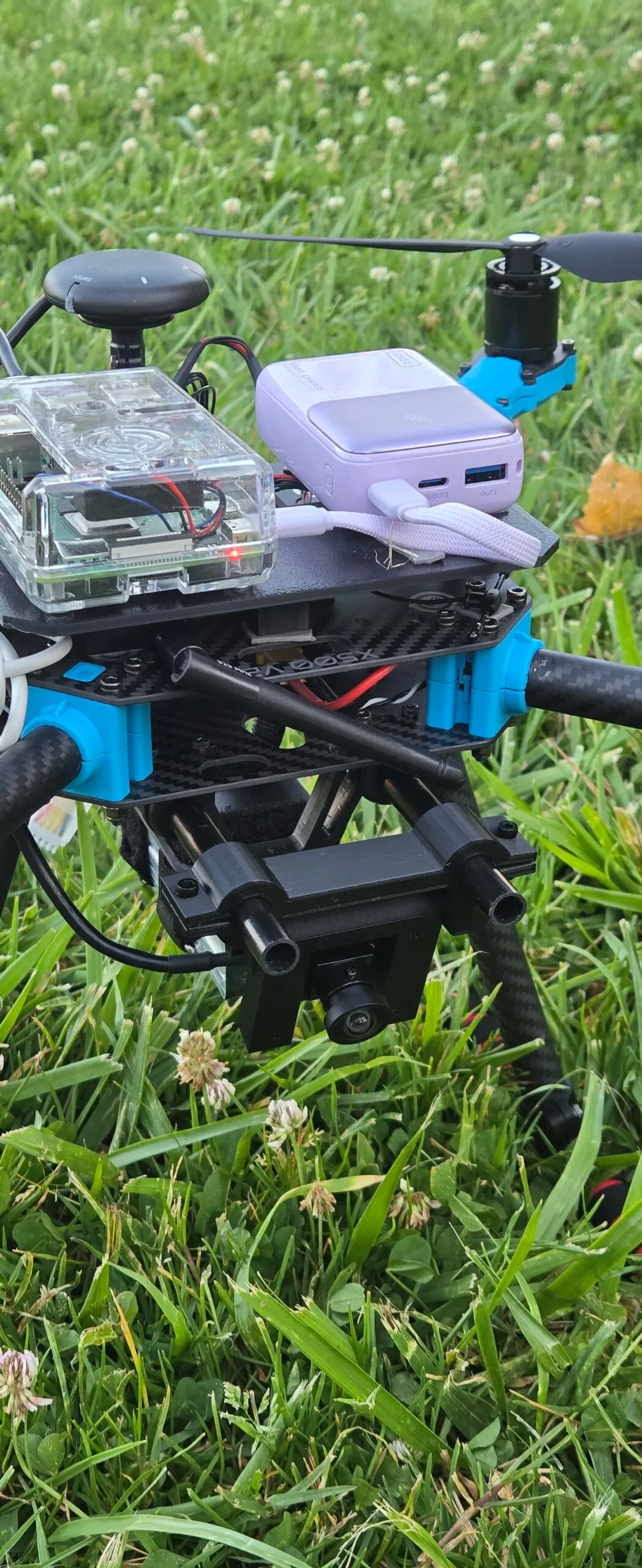
The drone is based on a Holybro X500 PX4 development kit with a Pixhawk 6C flight controller. I’m using a Raspberry Pi 4 as the companion computer. The Pi runs Ubuntu Server 24.04 and ROS 2 Jazzy.
The basic hardware stack:
Holybro X500 frame
Pixhawk 6C flight controller with PX4 firmware
Raspberry Pi 4 companion computer
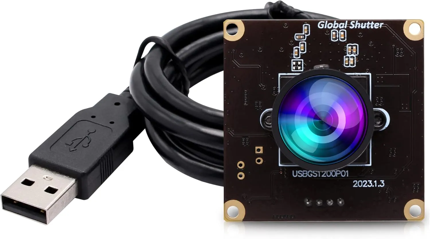
2 MP USB global-shutter camera
For RC Backup Controls:
RadioMaster Boxer ELRS RC Transmitter
RadioMaster ELRS RP1 Receiver
The Drone Architecture
The ROS 2 Pipeline
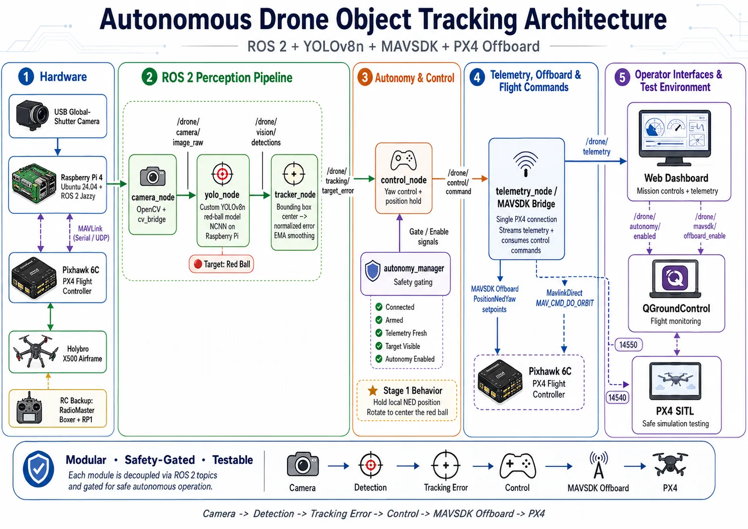
To tie everything together, the system runs on a modular ROS2 pipeline where each step of the process is handled by an independent node. The data flows cleanly down a publisher-subscriber chain: the Camera Node streams the raw video frames, the YOLO Node subscribes those frames to detect the red ball, the Tracker Node grabs the resulting bounding box to compute the X/Y center error, and the Control Node uses that error to fire off the final yaw commands.
Creating an ROS2 Node
ros2 pkg create --build-type ament_python <package_name>This generates a basic structure with:
package.xml- package metadatasetup.py- Python package configurationsetup.cfg- additional setup configurationresource/directory<package_name>/- your Python module directory
The Camera Node
Starting with the Camera Node
Before building the ROS 2 camera node, I tested the USB camera directly with OpenCV. This verified that the Raspberry Pi could see the camera, stream frames, and display the image at 15+ fps.
Show code
import cv2

camera_index = 0
cap = cv2.VideoCapture(camera_index, cv2.CAP_V4L2)

cap.set(cv2.CAP_PROP_FRAME_WIDTH, 640) cap.set(cv2.CAP_PROP_FRAME_HEIGHT, 480) cap.set(cv2.CAP_PROP_FPS, 30) cap.set(cv2.CAP_PROP_BUFFERSIZE, 1)

if not cap.isOpened():
    raise RuntimeError(f"Could not open camera index {camera_index}")
while True:
    ret, frame = cap.read()

    if not ret or frame is None:
        print("Failed to read frame")
        continue
cv2.imshow("USB Camera Test", frame)

    if cv2.waitKey(1) & 0xFF == ord("q"):
        break

cap.release()
cv2.destroyAllWindows()
Once the OpenCV camera test worked, I wrapped it into a ROS 2 node. The camera node reads frames with OpenCV, converts them with cv_bridge, and publishes them as sensor_msgs/Image.
Show code
PASTE CODE HEREThis became the first stage of the ROS 2 object tracking pipeline.
The Yolo Node
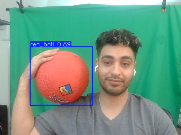
The next step was testing YOLOv8n directly on the camera feed. This let me validate inference, bounding boxes, confidence values, and frame rate before turning it into a ROS node.
Show code
from ultralytics import YOLO

MODEL_PATH = r"C:\Users\danie\Documents\Python\drone_object_tracker_ros\models\red_ball_ncnn_model"

model = YOLO(MODEL_PATH, task="detect")

results = model.predict(
    source=0,
    imgsz=320,
    conf=0.45,
    show=True,
    stream=True
)

for _ in results:
    pass
Training the Custom Red Ball YOLOv8 Model
For our red ball, I used a free Roboflow red ball dataset exported in YOLOv8n format. After downloading the dataset, the folder contained a data.yaml file plus the train/validation/test image folders.
A typical training script looked like this:
from ultralytics import YOLO

model = YOLO("yolov8n.pt")

results = model.train(
    data="red_ball_dataset/data.yaml",
    epochs=200,
    imgsz=640,
    batch=16,
    project="runs/detect",
    name="red_ball_v2",
)
For embedded deployment on the Raspberry Pi 4, I exported the trained model to NCNN:
yolo export \
  model=runs/detect/red_ball_v2/weights/best.pt \
  format=ncnn \
  imgsz=320
That produced an exported model folder that could be copied onto the Pi and loaded by the ROS 2 YOLO node. I tested different image sizes to trade off detection accuracy and speed:
yolo detect predict \
  model=runs/detect/red_ball_v2/weights/best_ncnn_model \
  source=0 \
  imgsz=320 \
  conf=0.5
yolo detect predict \
model=runs/detect/red_ball_v2/weights/best_ncnn_model \
source=0 \
imgsz=416 \
conf=0.5Image size of 416 worked well enough so I went with that.
ROS 2 YOLO Node
The YOLO node subscribes to the camera image topic, runs inference, filters for the target class, and publishes a custom DetectionArray message.
Show code
import time
from typing import List

import numpy as np
import rclpy
from cv_bridge import CvBridge
from rclpy.node import Node
from rclpy.qos import QoSProfile, ReliabilityPolicy, HistoryPolicy
from sensor_msgs.msg import Image
from ultralytics import YOLO

from drone_interfaces.msg import Detection, DetectionArray

class YoloNode(Node):
    def __init__(self):
        super().__init__("yolo_node")

        self.model_path = "models/red_ball_ncnn_model"
        self.confidence_threshold = 0.5
        self.iou_threshold = 0.45
        self.device = "cpu"
        self.input_size = 320
        self.target_class = "red ball"

        self.bridge = CvBridge()
        self.model = YOLO(self.model_path)

        image_qos = QoSProfile(
            reliability=ReliabilityPolicy.BEST_EFFORT,
            history=HistoryPolicy.KEEP_LAST,
            depth=1,
        )

        detection_qos = QoSProfile(
            reliability=ReliabilityPolicy.RELIABLE,
            history=HistoryPolicy.KEEP_LAST,
            depth=5,
        )

        self.image_sub = self.create_subscription(
            Image,
            "/drone/camera/image_raw",
            self.image_callback,
            image_qos,
        )

        self.detection_pub = self.create_publisher(
            DetectionArray,
            "/drone/vision/detections",
            detection_qos,
        )

    def image_callback(self, msg: Image):
        frame = self.bridge.imgmsg_to_cv2(msg, desired_encoding="bgr8")
        img_height, img_width = frame.shape[:2]

        results = self.model.predict(
            frame,
            conf=self.confidence_threshold,
            iou=self.iou_threshold,
            device=self.device,
            imgsz=self.input_size,
            verbose=False,
        )

        detection_array = DetectionArray()
        detection_array.stamp = msg.header.stamp
        detection_array.image_width = img_width
        detection_array.image_height = img_height

        detections: List[Detection] = []

        if results and len(results) > 0:
            result = results[0]

            if result.boxes is not None:
                boxes = result.boxes

                for i in range(len(boxes)):
                    cls_id = int(boxes.cls[i].item())
                    class_name = self.model.names.get(cls_id, f"class_{cls_id}")

                    if self.target_class and class_name.lower() != self.target_class:
                        continue

                    x1, y1, x2, y2 = boxes.xyxy[i].tolist()

                    pixel_cx = int((x1 + x2) / 2.0)
                    pixel_cy = int((y1 + y2) / 2.0)
                    pixel_w = int(x2 - x1)
                    pixel_h = int(y2 - y1)

                    detection = Detection()
                    detection.stamp = msg.header.stamp
                    detection.class_id = cls_id
                    detection.class_name = class_name
                    detection.confidence = float(boxes.conf[i].item())

                    detection.pixel_center_x = pixel_cx
                    detection.pixel_center_y = pixel_cy
                    detection.pixel_width = pixel_w
                    detection.pixel_height = pixel_h

                    detection.center_x = pixel_cx / img_width
                    detection.center_y = pixel_cy / img_height
                    detection.width = pixel_w / img_width
                    detection.height = pixel_h / img_height

                    detections.append(detection)

        detection_array.detections = detections
        detection_array.count = len(detections)

        self.detection_pub.publish(detection_array)
This converts raw camera frames into structured target detections that the rest of the drone autonomy stack can use.
The Tracker Node
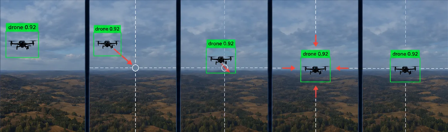
Tracker Node: Bounding Box to Error Signal
The tracker node converts YOLO bounding boxes into a normalized tracking error. The image center is treated as zero error. If the red ball is left or right of center, error_x becomes negative or positive. The control node then uses that value to rotate the drone.
raw_error_x = target_center_x - 0.5
raw_error_y = target_center_y - 0.5

normalized_error_x = raw_error_x * 2.0
normalized_error_y = raw_error_y * 2.0
The tracker also smooths the error with an exponential moving average:
class ExponentialMovingAverage:
    def __init__(self, alpha=0.4):
        self.alpha = alpha
        self.value = None

    def update(self, new_value):
        if self.value is None:
            self.value = new_value
        else:
            self.value = self.alpha * new_value + (1.0 - self.alpha) * self.value

        return self.value
The final target error message includes:
msg.error_x = filtered_error_x
msg.error_y = filtered_error_y
msg.target_visible = True
msg.target_confidence = detection.confidence
msg.target_area = detection.width * detection.height
msg.tracking_state = "LOCKED"
This creates a clean interface between perception and control.
The Control Node
The control node turns horizontal image error into a yaw rate command. The basic idea is:
error_x = apply_deadband(target.error_x, deadband_x)
desired_yaw_rate = error_x * gain_yaw
desired_yaw_rate = clamp(desired_yaw_rate, -max_yaw_rate, max_yaw_rate)
The actual logic is conservative. It only publishes real movement commands when autonomy is enabled, telemetry is fresh, the drone is connected, the drone is armed, and the target is visible.
def apply_deadband(value, deadband):
    if abs(value) < deadband:
        return 0.0

    sign = 1.0 if value > 0.0 else -1.0
    return sign * (abs(value) - deadband) / (1.0 - deadband)

def clamp(value, min_value, max_value):
    return max(min_value, min(value, max_value))
The Stage 1 controller holds the drone’s local NED position and only updates yaw:
error_x = apply_deadband(target.error_x, deadband_x)
desired_yaw = error_x * gain_yaw
yaw = clamp(desired_yaw, -max_yaw_rate, max_yaw_rate)

publish_position_hold(
    status="SENT",
    yaw_rate=yaw,
    source_error_x=target.error_x,
    source_error_y=target.error_y,
    update_yaw=True,
)
Instead of commanding forward/right/down velocity, the drone holds a captured local position:
command.position_valid = True
command.position_north = hold_position_north
command.position_east = hold_position_east
command.position_down = hold_position_down
command.yaw_deg = yaw_deg
command.yaw_rate = yaw_rate
This keeps the first real flight stage focused: hold position, rotate toward the red ball, and do not drift forward into the target.
The Telemetry Node: MAVSDK
The telemetry node owns the single MAVSDK connection to PX4. It streams telemetry from PX4 into ROS 2 and consumes /drone/control/command when Offboard mode is enabled.
The MAVSDK connection looks like this:
from mavsdk import System

drone = System()
await drone.connect(system_address=connection_url)

async for state in drone.core.connection_state():
    if state.is_connected:
        print("Drone connected")
        break
The bridge streams important telemetry:
async for battery in drone.telemetry.battery():
    battery_voltage = battery.voltage_v
    battery_remaining = battery.remaining_percent * 100.0
async for pv in drone.telemetry.position_velocity_ned():
local_position_valid = True
local_position_north = pv.position.north_m
local_position_east = pv.position.east_m
local_position_down = pv.position.down_masync for attitude in drone.telemetry.attitude_euler():
yaw_rad = math.radians(attitude.yaw_deg)MAVSDK Offboard Position Hold + Yaw
PX4 Offboard mode needs a setpoint before starting Offboard. The bridge primes Offboard by sending a local NED position hold setpoint first:
from mavsdk.offboard import OffboardError, PositionNedYaw

position_setpoint = PositionNedYaw(
    position_north_m,
    position_east_m,
    position_down_m,
    yaw_deg,
)

await drone.offboard.set_position_ned(position_setpoint)
await drone.offboard.start()
Then, while the target tracker is locked, the bridge keeps sending updated position/yaw setpoints:
await drone.offboard.set_position_ned(
    PositionNedYaw(
        hold_position_north,
        hold_position_east,
        hold_position_down,
        yaw_deg,
    )
)
This lets the drone hold its local position while rotating to center the red ball in the camera.
MAVLink / MavlinkDirect Orbit Command
For orbit behavior, I used MAVLink directly through MAVSDK’s MavlinkDirect interface. This lets the mission layer send MAV_CMD_DO_ORBIT with orbit radius, speed, yaw behavior, and number of revolutions.
MAV_CMD_DO_ORBIT = 34
MAV_COMP_ID_AUTOPILOT1 = 1

ORBIT_YAW_BEHAVIOR_VALUES = {
    "HOLD_FRONT_TO_CIRCLE_CENTER": 0,
    "FRONT_TO_CIRCLE_CENTER": 0,
    "HOLD_INITIAL_HEADING": 1,
    "UNCONTROLLED": 2,
    "HOLD_FRONT_TANGENT_TO_CIRCLE": 3,
    "RC_CONTROLLED": 4,
}
The command calculates orbit angle from revolutions:
revolutions = float(command.orbit_revolutions)
orbit_angle_rad = 0.0 if revolutions <= 0.0 else revolutions * 2.0 * math.pi
Then it builds a MAVLink COMMAND_LONG message:
fields = {
    "target_system": 1,
    "target_component": MAV_COMP_ID_AUTOPILOT1,
    "command": MAV_CMD_DO_ORBIT,
    "confirmation": 0,
    "param1": radius_m,
    "param2": velocity_m_s,
    "param3": float(yaw_behavior),
    "param4": orbit_angle_rad,
    "param5": latitude_deg,
    "param6": longitude_deg,
    "param7": absolute_altitude_m,
}
And sends it through MavlinkDirect:
from mavsdk.mavlink_direct import MavlinkMessage
import json

message = MavlinkMessage(
    "COMMAND_LONG",
    0,
    0,
    int(fields["target_system"]),
    int(fields["target_component"]),
    json.dumps(fields, allow_nan=False),
)

await drone.mavlink_direct.send_message(message)
This keeps the normal flight logic high-level through MAVSDK, while still allowing lower-level MAVLink commands when MAVSDK does not expose every parameter needed for the mission.
System Launch Example
To build the ROS2 system on the Pi we use colcon:
cd ~/drone_ws
colcon build --symlink-install
source install/setup.bash
In simulation, the ROS 2 system connects to PX4 SITL over UDP:
cd ~/drone_ws
source ~/venv/bin/activate
source /opt/ros/jazzy/setup.bash
source install/setup.bash

ros2 launch drone_bringup full_system_launch.py \
  connection_url:=udp://:14540 \
  allow_mavsdk_actions:=true
On real hardware, the Pi connects to the Pixhawk over serial:
cd ~/drone_ws
source ~/venv/bin/activate
source /opt/ros/jazzy/setup.bash
source install/setup.bash

ros2 launch drone_bringup full_system_launch.py \
  connection_url:=serial:///dev/ttyACM0:57600
The main topics are:
/drone/camera/image_raw
/drone/vision/detections
/drone/tracking/target_error
/drone/control/command
/drone/telemetry
/drone/autonomy/enabled
/drone/mavsdk/offboard_enable
/drone/mavsdk/command_status
The result is a modular ROS 2 autonomy stack where each node has one job:
Camera Node
    -> publishes image frames

YOLO Node
    -> detects the red ball

Tracker Node
    -> converts bounding box center into normalized error

Control Node
    -> converts error_x into yaw command

Telemetry / MAVSDK Bridge
    -> sends safe PX4 Offboard setpoints
This makes the system easier to test, debug, and expand into future missions like approach, orbit, return-to-launch, and landing.
SITL Simulation
Software-in-the-Loop (SITL) simulation is a critical testing framework that allows you to run the actual drone autopilot software (like PX4 or ArduPilot) on your computer without needing physical hardware. It mimics the physics of a real drone and its environment, letting you safely test your MAVSDK scripts, navigation logic, and safety fail-safes in a virtual world. Using SITL prevents costly hardware crashes during the development phase, ensuring your code is stable and reliable before you ever deploy it to a physical drone.
I run this in WSL/Ubuntu 24 LTS:
sudo docker run --rm -it --network host px4io/px4-sitl:latestWhen I launch the ROS2 system in SITL, I change the connection from usb to udp port 14540. QGroundControl will be using port 14550.
I run this on the Pi:
ros2 launch drone_bringup full_system_launch.py connection_url:=udp://:14540 allow_mavsdk_actions:=true