Building a Pure-Python ROS 2 Driver for the YDLIDAR X2
Code on GitHubThis is a pure-Python driver and ROS 2 Jazzy package that reads the LiDAR, decodes complete revolutions, publishes sensor_msgs/msg/LaserScan messages, creates the required TF transform, and launches RViz with a saved configuration.
Github: https://github.com/danielengineer92/YDLIDARX2-ROS2
Starting with the serial protocol
Before adding ROS 2, I needed reliable data from the sensor itself. The X2 sends a continuous binary stream at 115200 baud. The Python driver searches for the AA 55 packet header, reads each variable-length packet, validates its 16-bit XOR checksum, and decodes the packed distance and angle values.
A single packet only contains part of the circle, so the driver keeps reading packets until it reaches the marker for the next revolution. It then returns one complete collection of polar-coordinate points.
Keeping this logic in a ROS-independent driver.py file was a useful design choice. I could test packet parsing with a fake serial port before involving ROS, RViz, TF, or even the physical LiDAR.

Turning the driver into a ROS 2 node
The next step was wrapping the Python driver in an rclpy node. The node opens the configured serial port, waits for a complete revolution, converts the raw points into a LaserScan, and publishes the result on /scan.
ROS laser scans are more structured than a list of arbitrary points. The message describes evenly spaced angles from angle_min to angle_max, and the ranges array must have one value for each direction. I created a fixed number of angular bins and mapped every raw point into the matching array index.
Empty bins are filled with math.inf, which is the normal ROS representation for a direction with no valid return. If multiple measurements land in the same bin, I keep the nearest one because that is the safest value for future obstacle detection.
index = int((angle - angle_min) / angle_increment)

if 0 <= index < bin_count:
    ranges[index] = min(ranges[index], distance)
I also added ROS parameters for the serial port, frame name, distance limits, and output bin count. This lets me tune the node from a launch command instead of editing Python every time.
Measuring instead of guessing
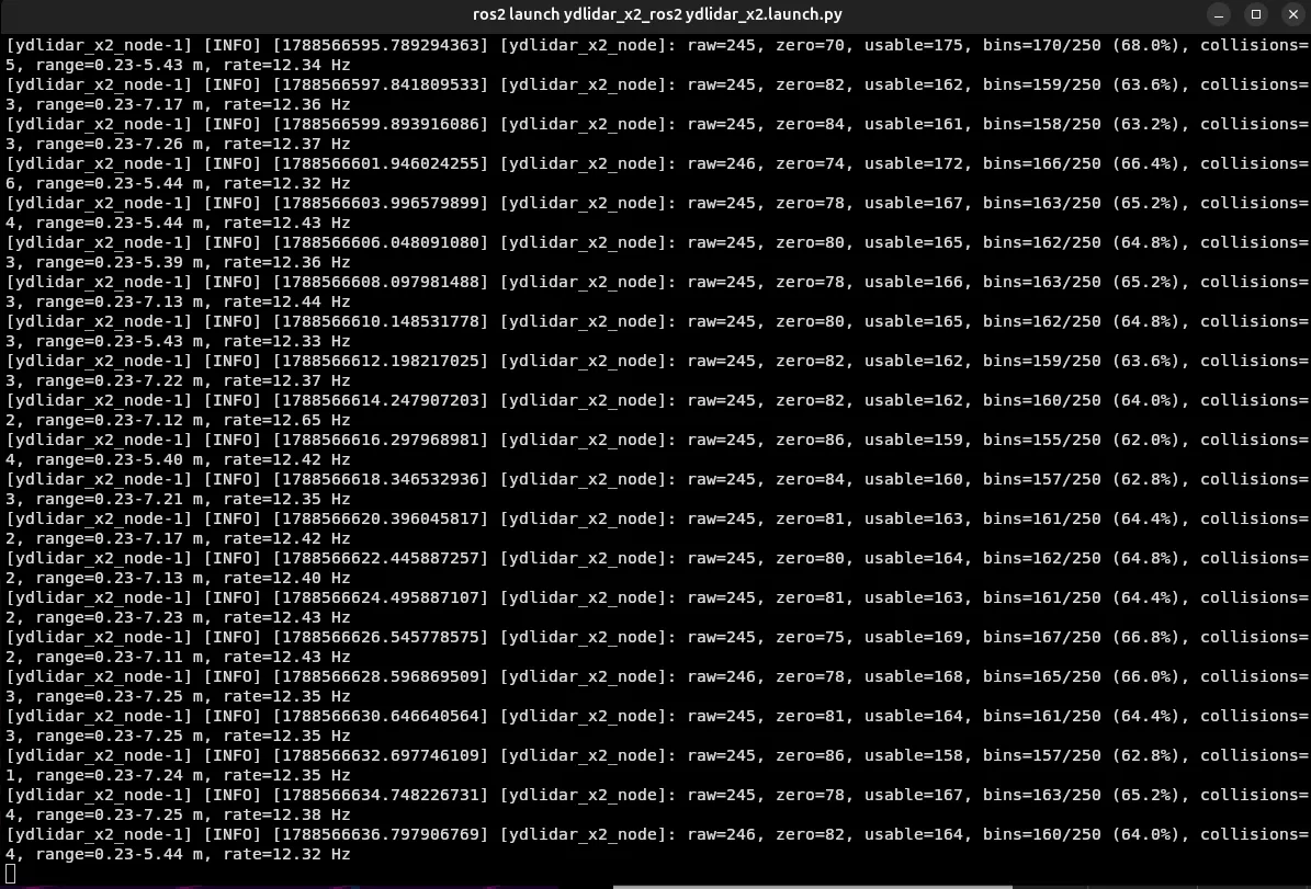
At first I used 360 output bins because a full circle contains 360 degrees. That did not mean the X2 was actually producing 360 measurements per revolution. I added diagnostics to count the raw points, zero-distance returns, usable measurements, filled bins, bin collisions, measured range, and scan frequency.
In my test environment, a typical steady-state revolution looked like this:
raw=247, zero=62, usable=185, bins=181/250 (72.4%), collisions=4, range=0.29-5.35 m, rate=12.22 HzThose measurements helped me settle on 250 bins as a practical default. It is close to the number of raw samples being received, while still leaving a predictable, evenly spaced output array. Reducing the bin count increases coverage but also causes more points to collide in the same bin. Increasing it creates more empty directions without creating new physical measurements.
Fixing coordinate conventions
One of the most interesting bugs was that left and right appeared mirrored. The X2’s angles increase clockwise, while ROS uses counter-clockwise-positive angles. Negating the raw angle reverses that direction.
angle = math.radians((-point.angle_deg) % 360.0)

if angle >= math.pi:
    angle -= 2.0 * math.pi
The modulo operation wraps a negative angle back into one positive revolution. For example, -90 % 360 becomes 270. The following subtraction expresses the upper half of the circle as negative angles, producing the conventional ROS range from -pi to +pi.
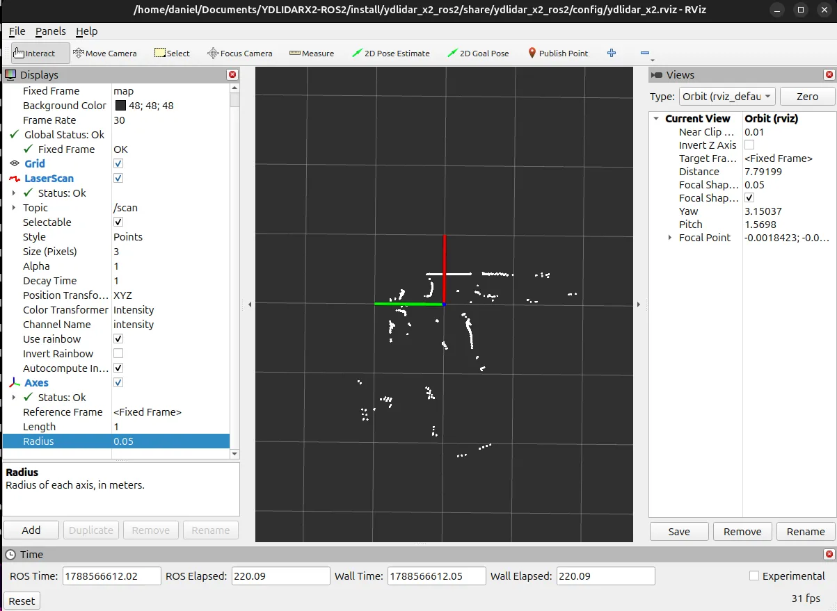
This was also a good reminder that a rotated RViz camera can make correct data look wrong. I added an Axes display and aligned the view so red X represents forward and green Y represents left before judging the sensor orientation.
Launching the complete system
Running the driver, publishing a transform, and opening RViz in separate terminals worked, but it was repetitive. I created a Python launch file that starts all three pieces together:
ydlidar_x2.launch.py
├── ydlidar_x2_node          reads the sensor and publishes /scan
├── ydlidar_x2_static_tf     connects map to ydlidar_x2_link
└── rviz2                    loads the saved LiDAR display
The RViz configuration is stored inside the package and installed by setup.py. I used FindPackageShare and PathJoinSubstitution in the launch file so the config is found through the ROS package index instead of a hard-coded path on my computer.
Now the whole stack starts with one command:
ros2 launch ydlidar_x2_ros2 ydlidar_x2.launch.pyProblems I worked through
This project gave me hands-on experience with several real ROS and Linux issues:
- My account needed membership in the Linux
dialoutgroup. - A minimal ROS installation was missing the
ros2 runandros2 launchCLI extensions. - Launch files must be explicitly installed through an
ament_pythonpackage’ssetup.py. - A
LaserScanframe name does not create a TF transform by itself. - Calling ROS shutdown twice can raise an exception during
Ctrl+Ccleanup. - RViz can drop messages while it waits for a valid transform.
- Sensor coordinates and ROS coordinates may use opposite angular directions.
Working through those failures taught me more than a perfectly smooth demo would have. I now understand how a ROS 2 Python package connects its node, entry point, package metadata, launch files, parameters, topics, TF frames, and visualization configuration.
Short Tutorial: Run the Project
This project was tested on Ubuntu 24.04 with ROS 2 Jazzy.
Github: https://github.com/danielengineer92/YDLIDARX2-ROS2
1. Clone the repository
cd ~/Documents
git clone https://github.com/danielengineer92/YDLIDARX2-ROS2.git
cd YDLIDARX2-ROS2
2. Install package dependencies
source /opt/ros/jazzy/setup.bash
rosdep install --from-paths src --ignore-src -r -y
3. Connect and locate the LiDAR
Plug in the X2 and check its serial device:
ls -l /dev/ttyUSB* /dev/ttyACM* 2>/dev/null
ls -l /dev/serial/by-id/ 2>/dev/null
The default launch configuration expects /dev/ttyUSB0.
If the serial port reports a permission error, add your account to dialout, then log out and back in:
sudo usermod -aG dialout "$USER"4. Build and source the workspace
source /opt/ros/jazzy/setup.bash
colcon build --symlink-install --packages-select ydlidar_x2_ros2
source install/setup.bash
5. Launch the LiDAR and RViz
ros2 launch ydlidar_x2_ros2 ydlidar_x2.launch.pyTo use a different serial device or bin count:
ros2 launch ydlidar_x2_ros2 ydlidar_x2.launch.py \
  port:=/dev/ttyUSB1 \
  angle_bins:=180
6. Inspect the scan
Open another terminal:
cd ~/Documents/YDLIDARX2-ROS2
source /opt/ros/jazzy/setup.bash
source install/setup.bash

ros2 topic hz /scan
ros2 topic echo /scan --once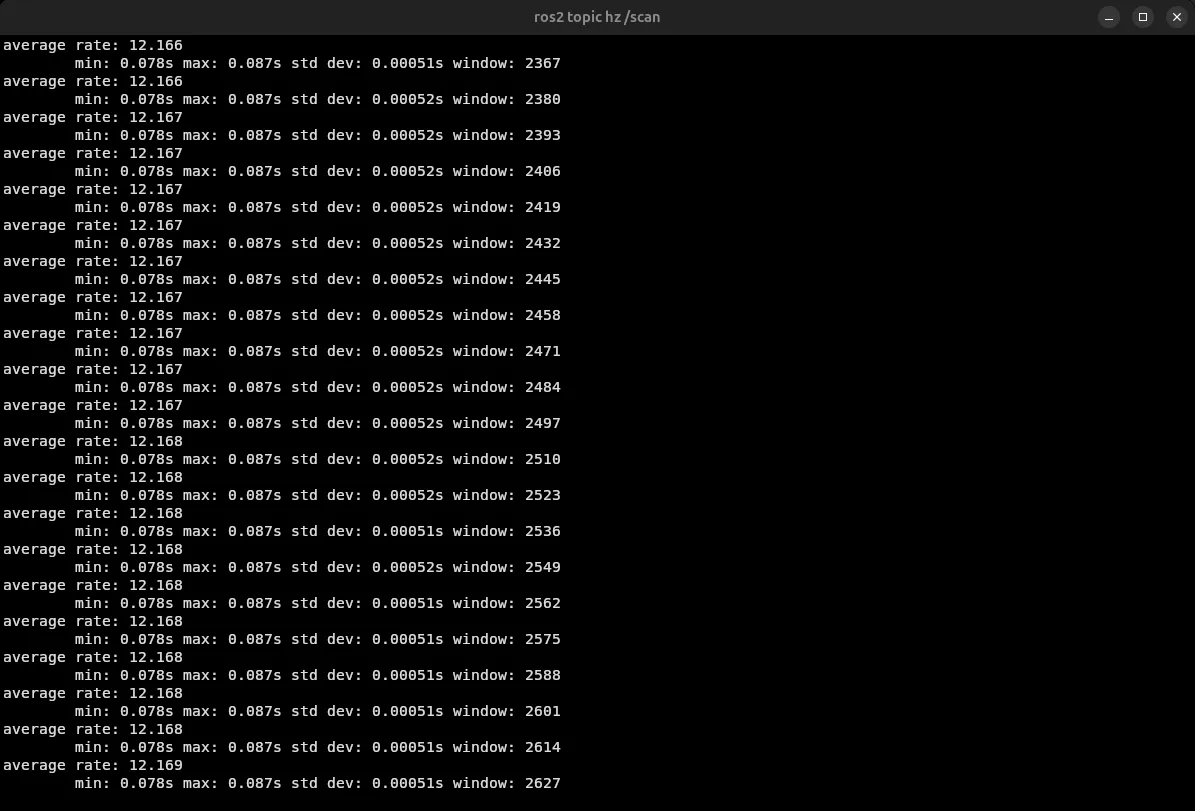
7. Run the hardware-free tests
source /opt/ros/jazzy/setup.bash
source install/setup.bash
python3 -m pytest src/ydlidar_x2_ros2/test/test_driver.py -q
Expected result:
13 passedWhat I want to build next
The next step is a ROS 2 subscriber that reads /scan and reports the closest obstacle in front of the robot. That will turn this project from a sensor driver into the beginning of a perception and navigation system.
The complete source code and detailed setup guide are available in my YDLIDARX2-ROS2 repository.